Contact Us
|
WeChat
WeChat ID:842122368Scan to Connect
WeChat ID:842122368Scan to Connect

Radio frequency performance is determined by more than a single output-power figure. For engineers developing professional RF equipment, a power amplifier must be evaluated as part of a complete system, with attention to frequency coverage, gain consistency, electrical requirements, thermal conditions, monitoring interfaces, and mechanical integration.
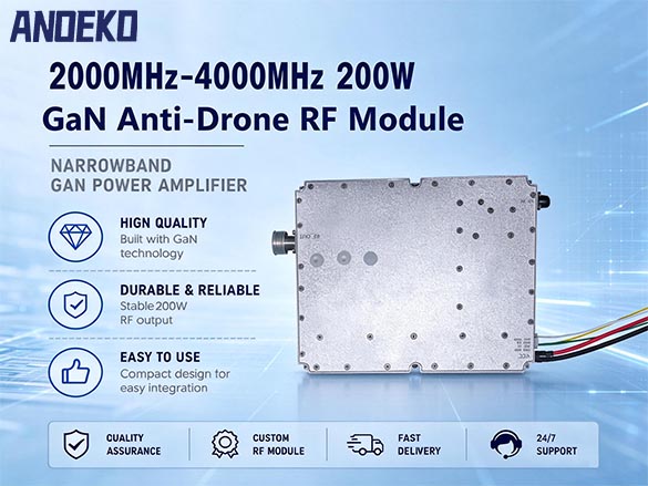
ANOEKO’s 2000–4000MHz RF power amplifier module is designed for integration into professional RF platforms that require amplification across the 2–4 GHz frequency range. With a stated maximum output power of 200W, a compact mechanical format, and interfaces for RF input, RF output, power supply, and control communication, the module provides a defined hardware platform for system-level engineering.
This article examines the principal specifications and integration considerations of the 2000–4000MHz 200W RF amplifier module. It also explains how engineers can assess a wideband RF amplifier datasheet, compare different amplifier technologies, and determine whether a particular module is suitable for their equipment requirements.

Frequency coverage is one of the first specifications engineers should examine when evaluating an RF power amplifier module. The 2000–4000MHz range spans a substantial portion of the microwave spectrum and is relevant to a variety of professional RF equipment, laboratory platforms, and specialized wireless system designs.
A module designed for this range offers a defined operating window for system developers. Rather than selecting a component based only on its nominal center frequency, engineers should verify the complete frequency range and establish whether the required performance is maintained across the intended operating band.
This distinction is important when comparing a conventional narrowband amplifier with a wideband RF amplifier module. A product may support a broad frequency range on paper, but the practical value of that coverage depends on how its gain, output power, matching characteristics, and thermal behavior are specified and verified.
For ANOEKO, the 2000–4000MHz model forms part of a broader RF module product category. Depending on the project, engineers may also evaluate other frequency segments and output-power classes. The correct selection should be based on the equipment specification rather than on a broad product label alone.
The stated maximum output power of this module is 200W. For an RF power amplifier, however, output power should never be considered in isolation.
Before selecting a 200W RF amplifier module, engineers should establish the conditions under which the rating applies. These may include the input drive level, operating frequency, signal type, duty cycle, ambient temperature, cooling arrangement, and permitted variation across the frequency band.
A maximum rating does not automatically mean that identical performance will be available under every operating condition. Continuous-wave performance, modulated-signal performance, and short-duration peak output may require different specifications and test methods.
The product data supplied for this model lists a typical operating voltage of 32V and includes a current requirement. Those electrical values must be reconciled with the stated 200W output rating and the specified efficiency before the datasheet is finalized. Buyers should request the confirmed supply-current requirement and the exact conditions used to measure output power.
This verification step is essential for equipment manufacturers planning their power budget, thermal design, enclosure, and overall system architecture. A reliable RF amplifier specification should make the relationship between RF output power and DC input requirements clear.
The supplied specification lists a maximum gain of 48dB and gain flatness of no more than 5dB. These are important parameters when evaluating an RF power amplifier module for wideband operation.
Gain describes the relationship between the input signal level and the output signal level under specified measurement conditions. Gain flatness describes how much that gain varies across the stated frequency range.
For an amplifier intended to cover 2000–4000MHz, full-band performance is more informative than a single gain value measured at one frequency. Engineers should look for gain data across the band and confirm the conditions used to obtain the reported maximum gain and gain-flatness figures.
A useful datasheet should also identify whether the measurements are typical or guaranteed limits. Where available, frequency-sweep plots can help engineers understand how performance changes between the lower, middle, and upper portions of the operating band.
When comparing RF power amplifier modules, buyers should therefore evaluate the combination of output power, gain, gain flatness, and operating conditions. A higher headline gain or output-power rating does not automatically make one module more suitable than another.
The supplied data lists an input-port voltage standing wave ratio (VSWR) of no more than 2, measured with the module unpowered using a network analyzer.
VSWR is a commonly used indicator of impedance matching. It describes the relationship between forward and reflected waves at a specified reference plane. For engineers integrating an RF amplifier module, the measurement frequency range and test configuration are as important as the numerical result.
An unpowered input-port measurement should not be confused with a powered operating measurement. The final product documentation should identify the test condition clearly and distinguish input-port matching from output-port matching wherever both are specified.
The standard input power is listed as 5dBm. The supplied maximum non-damaging input-power entry also requires confirmation before publication, because its notation does not clearly establish the permitted input limit.
For system integrators, a clear input-power specification helps define the interface between the signal source and the amplifier. It should be supported by the manufacturer's confirmed operating limits and handling instructions.
High-power RF equipment requires careful coordination between electrical supply capacity and heat management. A compact module may simplify mechanical integration, but the complete assembly still needs to accommodate its electrical and thermal requirements.
The supplied specification identifies 32V as the nominal operating voltage and lists a supply requirement of at least 20A. It also reports 20% amplifier efficiency at 200W output and gives a separate typical current figure of 16A. These values are not mutually consistent under a straightforward DC-input-to-RF-output calculation and must be reviewed by the engineering team before the article or product datasheet is published.
The efficiency definition should also be stated explicitly. Depending on the measurement method, a document may refer to drain efficiency, collector efficiency, or power-added efficiency. These metrics are not interchangeable.
Thermal design should be evaluated using the confirmed electrical input power, output-power conditions, efficiency definition, mounting arrangement, and cooling requirements. System developers should follow the manufacturer's installation and thermal-management guidance and verify performance under the intended operating environment.
A well-prepared RF amplifier datasheet should make these relationships transparent. Clear specifications help OEM teams plan power supplies, enclosure layouts, thermal interfaces, and acceptance tests without relying on assumptions.
The supplied operating-temperature range is −10°C to +55°C. The data also lists power stability of ±1.0dB over a range extending from −40°C to +55°C.
These two statements should be reconciled before publication. If the amplifier is rated for operation from −10°C to +55°C, the separate −40°C condition must be clearly identified as a storage condition, a test condition, or a different operating specification, as applicable.
Temperature can influence the performance of RF components and the thermal behavior of a complete assembly. For this reason, engineers should evaluate the declared operating range alongside the specified output-power conditions, cooling arrangement, and any applicable derating guidance.
Where a manufacturer provides temperature-test results, the documentation should explain what was measured, how the measurement was conducted, and which limits were verified. This makes the results more useful for professional buyers and system integrators.
The module specification identifies an RS-485 communication protocol and monitoring functions for temperature, current, voltage, and RF output power. The control connector is described as a 2.54mm-pitch, 2 × 4 header.
These functions can be valuable in equipment designs that need access to operating-status information. A monitoring interface can help the host system collect diagnostic data and support maintenance workflows, provided the protocol and measurement definitions are documented.
Before integration, engineering teams should confirm the communication protocol details, connector pinout, electrical levels, supported commands, update behavior, and measurement accuracy. They should also establish whether the listed measurements are available continuously, on request, or only under specified operating conditions.
The presence of an RS-485 interface does not by itself define the complete software integration. A clear interface-control document helps reduce ambiguity during development and makes it easier for different teams to work with the same hardware.
The supplied mechanical dimensions are 170 × 137.5 × 26.5mm. The RF input is specified as SMA, while the RF output is specified as an N-type female connector. The power interface is described as a feedthrough capacitor.
These details should be considered early in the design process, particularly when the amplifier is being incorporated into a larger enclosure or an existing RF platform.
Engineers should verify whether the published dimensions include the connectors, identify the connector variants, and obtain a mechanical drawing showing mounting-hole positions and tolerances. The supplied mounting-hole information requires clarification before it can be reproduced in a final datasheet.
Connector selection, cable compatibility, mounting geometry, and access for installation all affect the practicality of system integration. Accurate drawings and unambiguous interface definitions are therefore important parts of a complete RF module specification.
GaN and LDMOS are both used in RF power amplification, but the suitability of either technology depends on the operating frequency, output-power target, efficiency requirements, linearity, thermal constraints, cost, and overall system design.
A GaN RF amplifier module may be considered when the design requirements and operating conditions align with the capabilities of the selected GaN device. An LDMOS RF amplifier module may be suitable for other frequency and power combinations. Neither technology should be treated as universally superior without reference to the actual design and test data.
For this reason, buyers comparing a GaN anti-drone module with an LDMOS anti-drone module should examine verified specifications rather than relying on technology labels alone. Relevant factors include operating frequency, rated output power, gain flatness, efficiency definition, input matching, supply requirements, thermal limits, interfaces, and mechanical dimensions.
ANOEKO offers RF module options across different frequency ranges and power classes. The appropriate product should be selected against the confirmed requirements of the target system, with any technology-specific claims supported by product documentation.
Not every equipment project uses the same enclosure, connector arrangement, control interface, or operating conditions. For this reason, RF module buyers may need to discuss integration requirements with the manufacturer before finalizing a design.
ANOEKO can be contacted to discuss whether a particular project requires a different mechanical arrangement, interface configuration, or other product variation. The availability and feasibility of each customization should be confirmed for the specific model and order.
A productive technical review should begin with a clear requirements document. This can include the target frequency range, output-power requirement, input conditions, power-supply limits, environmental range, mechanical envelope, monitoring requirements, and applicable compliance obligations.
OEM and ODM discussions are most effective when both parties work from a consistent set of verified specifications. This approach also helps avoid confusion between standard product features and optional modifications.
When evaluating a 200W RF amplifier module for a professional system, buyers should request a current datasheet and confirm the following items:
The operating frequency range and the conditions under which rated output power is achieved.
The definition of output power and amplifier efficiency.
The specified gain and gain-flatness limits across the band.
The input-power operating range and the confirmed non-damaging input limit.
Input and output VSWR, including the measurement conditions.
Nominal voltage, required current, and expected DC input power.
Operating temperature, thermal-management requirements, and any derating guidance.
Communication protocol details, connector pinout, and monitoring capabilities.
Mechanical drawings, connector variants, mounting-hole dimensions, and tolerances.
Any required compliance documentation for the intended application and destination market.
This checklist supports a more meaningful comparison between products. It also helps engineering teams distinguish between a headline specification and a complete, integration-ready hardware definition.
ANOEKO’s 2000–4000MHz RF power amplifier module provides a defined starting point for engineering teams evaluating RF amplification hardware in the 2–4 GHz range. Its supplied specification identifies a 200W maximum output-power rating, 48dB maximum gain, gain flatness of no more than 5dB, SMA input, N-type female output, RS-485 monitoring, and a compact mechanical format.
The electrical and environmental figures should be reconciled in the final datasheet before the product is promoted with firm performance claims. In particular, output power, supply current, efficiency, temperature range, and input-power limits should be presented with consistent definitions and test conditions.
For engineers comparing an RF amplifier module, a wideband RF module, or a customized RF amplifier for professional system integration, the most useful next step is a specification-based technical review. ANOEKO can provide further product information so that buyers can assess whether this 2000–4000MHz model matches their verified design requirements.
Product suitability, configuration options, and compliance requirements should be confirmed with the manufacturer for each intended application. Any RF transmission or counter-UAS deployment must also comply with applicable spectrum, equipment, and operational regulations.
Consultation Hotline
+86 18948793112
Email:lisen1205@foxmail.com
Mobile:+86 18948793112
WhatsApp:+86 18948793112
Address:Changchun North Road, Gongming Street, Guangming District, Shenzhen, China
Copyright © Copyright 2013 Anoeko Technology Co., Ltd. All Rights Reserved. | Anti-Drone & Low-Altitude Defense Experts ICP:ICP